 |
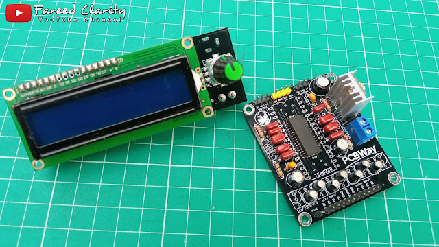
| Volume & Tone Control Digital TEA6320 Arduino LCD Rotary Encoder |
When I opened the storage area for various kinds of electronic circuit PCBs, I saw a used car audio mainboard and focused on an IC to control the audio part with the IC code, namely TEA6320, to find out the specifications of the IC I tried to open the datasheet and it turned out that the IC was controlled using a microcontroller with I2C DATA COMMUNICATION LINES (SDA & SCL) so without a microcontroller the IC cannot be used manually easily. For this reason, I started to study the datasheet and looked for various information to be used as a reference after that I just started designing the PCB layout from the scheme obtained from the TEA6320 ic datasheet.
 |
| Used Car Audio mainboard |
 |
| IC SMD TEA6320 |
The TEA6320 IC that I got from the used car audio mainboard is of the SMD type which of course in making the PCB layout I have to use SMD footprints but I also include DIP components in making the layout so that later the PCB becomes universal which means that if there is no SMD component then I can use the DIP component and vice versa. The layout that I made using the scheme from the TEA6320 sound fader IC datasheet with a power supply of about 7.5 to 9.5 volts then I used a 7808 linear regulator IC even though from the datasheet this ic only requires a small current, which is only 26mA at a voltage of 8.5 volts. The use of the 7808 ic regulator is so that the input power supply can be more flexible.
This TEA6320 IC has:
- Four stereo input options and one mono input that can be controlled by software.
- MUTE control zero crossing audio signal that can be controlled by software (i2c) or hardware (Pin).
- Tone control BASS, TREBLE and LOUDNESS that can be controlled by software.
- Four stereo outputs, front and rear stereo.
- I2C data communication path (SDA - SCL) to control the functions of IC TEA6320.
- Interface for noise reduction circuits.
- Interface for External Equalizer.
- Volume, Ballance & Fader Control.
- Special character loudness is automatically controlled in combination with the volume setting.
- Power Supply with internal power-on reset.
As explained above that the layout is made from the original schema of the datasheet and the layout is made so that it can use both types of ICs, both SMD and DIP types, the layout is a bit complex with the top down track path aka dual layer layout which of course it is impossible to make its own pcb like making pcbs in previous projects, for that the PCB layout I will print on the site PCBWay.com.
Here is the scheme and of course the layout will be printed into a pcb.
 |
| TEA6320 Sound Fader Scheme |
 |
| Layout PCB Sound Fader TEA6320 |
To download or print the pcb directly on the site PCBWay.com The gerber file please download below.
I select pcb fabrication on the site PCBWay.com is because of the ease and relatively affordable printing cost, which is only 5 dollars, we can get 5 or even 10 pcb pieces so I make a pcb every time I make a pcb it is always printed there, uh yes another one if you have never printed a pcb there and want to try then when registering an account PCBWay for the first time there will be a welcome bonus balance of 5 dollars for your first print fee, so your first print fee is as if it were free so please register an account PCBWay right now through tautan ini.
 |
| PCBWay.com |
 |
| Welcome bonus for first account registrants |
In addition to printing the TEA6320 main PCB which must be microcontroller controlled, I also print a PCB for the controller which is also a viewer panel equipped with a rotary encoder as the setting, I made this control panel universal so that it can be used for other projects by adding pinheads for all the microcontroller pinouts and of course the layout is dual layer as well, below I include the schemes and layouts that I have designed.
 |
| Universal scheme of control panel |
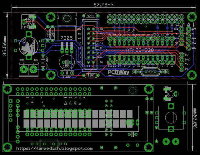 |
| Rear Front Control Panel Universal Layout |
Well when the main PCB TEA6320 along with the PCB Control display has been finished the layout has been made and has also been finished printing into a PCB in PCBWay then this is what the result looks like.
 |
| PCB Sound Fader TEA6320 |
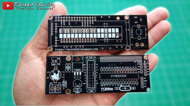 |
| PCB Universal Control Panel Front Rear |
 |
| Volume & Tone Control Digital TEA6320 Arduino LCD Rotary Encoder |
Also read : Membuat Amplifier TDA7388 Quad Bridge 180W dilengkapi PreAmp
After it was finished assembling, it could not be used immediately without a program that could control it, so I also studied the TEA6320 IC datasheet to find out how to control all the functions on the IC and it turned out that in fact out there there were already people who made libraries for Arduino, with the Arduino library we can more easily make the program, the program to control the TEA6320 IC I personalize as desired and I display the menu:
1. The volume on the 16X2 LCD display on the first line is displayed with the words VOLUME along with a level value between 1 and 50 and a gain value between - 31 to 30 in the form of decibels (dB) while the second line displays a bar and speaker animation.
 |
| Volume Display |
2. The bass on the 16X2 LCD display on the first line is displayed with the words BASS along with a level value between 1 and 30 and a gain value between - 15 to 15 in the form of decibels (dB) while the second line displays bars and tone animations.
 |
| Bass View |
3. The treble on the 16X2 LCD display on the first line is displayed with the words TRBL along with a level value between 1 and 24 and a gain value between - 12 to 12 in the form of decibels (dB) while the second line displays bars and tone animations.
 |
| Tampilan Treble |
4. Automatically controlled loudness is combined with volume settings.
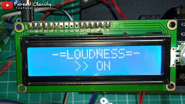 |
| Loudness Display |
5. Input selectors 1 to 4 stereo inputs.
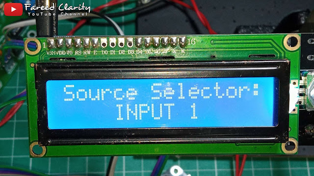 |
| Input source selection view |
6. Mute will activate when the switch on the rotary encoder is pressed for a long time.
 |
| Display when Mute is active |
For the program code, please see below or it can also be at Download pada tautan ini as well as a library for its Arduino header.
#include < Wire.h>
#include < MsTimer2.h>
#include < Encoder.h>
#include < EEPROM.h>
#include < TEA6320.h>

#include < liquidcrystal_i2c .h="">  // library LCD

#define MUTE 10
#define SW 4

TEA6320 tea;

Encoder myEnc( 3, 2 ); //CLK, DT encoder connection

LiquidCrystal_I2C lcd(0x27, 16, 2); // Set Alamat I2C LCD dan type LCD

byte a1[ 8 ] = { 0b00000, 0b11011, 0b11011, 0b11011, 0b11011, 0b11011, 0b11011, 0b00000 };
byte a2[ 8 ] = { 0b00000, 0b11000, 0b11000, 0b11000, 0b11000, 0b11000, 0b11000, 0b00000 };
byte a3[ 8 ] = { 0b00000, 0b00000, 0b00000, 0b11011, 0b11011, 0b00000, 0b00000, 0b00000 };
byte spk[ 8 ] = { 0b00000,
                  0b00001,
                  0b00011,
                  0b01111,
                  0b01111,
                  0b00011,
                  0b00001,
                  0b00000
                };
byte spkOn1[ 8 ] = { 0b00000,
                     0b00000,
                     0b01000,
                     0b00100,
                     0b00100,
                     0b01000,
                     0b00000,
                     0b00000
                   };
byte spkOn2[ 8 ] = { 0b00100,
                     0b00010,
                     0b00001,
                     0b00001,
                     0b00001,
                     0b00001,
                     0b00010,
                     0b00100
                   };
byte tone1[ 8 ] = { 0b11100,
                    0b11110,
                    0b01000,
                    0b00100,
                    0b00010,
                    0b01110,
                    0b11110,
                    0b01100
                  };
byte tone2[ 8 ] = { 0b00010,
                    0b00011,
                    0b00010,
                    0b01110,
                    0b11110,
                    0b01100,
                    0b00000,
                    0b00000
                  };

unsigned long newPosition, time, oldPosition = - 999;
int  menu, w, vol, loud, vol_d, z, bass, bass_d, treb, treb_d, in , mute, m;


// constants won't change. They're used here to set pin numbers:
//const int BUTTON_PIN = 7; // the number of the pushbutton pin
const int SHORT_PRESS_TIME = 500; // 1000 milliseconds
const int LONG_PRESS_TIME  = 500; // 1000 milliseconds

// Variables will change:
int lastState = HIGH;  // the previous state from the input pin
int currentState;     // the current reading from the input pin
unsigned long pressedTime  = 0;
unsigned long releasedTime = 0;
bool gantian;


void setup( ) {
  Serial.begin( 9600 );
  Wire.begin( );
  //lcd.begin( 16, 2 );
  lcd.begin();
  lcd.backlight();
  lcd.createChar( 0, a1);
  lcd.createChar( 1, a2 );
  lcd.createChar( 2, a3 );
  lcd.createChar( 3, spk );
  lcd.createChar( 4, spkOn1 );
  lcd.createChar( 5, spkOn2 );
  lcd.createChar( 6, tone1 );
  lcd.createChar( 7, tone2 );

  pinMode( SW, INPUT_PULLUP); // ENCODER BUTTON
  pinMode( MUTE, INPUT_PULLUP ); // MUTE

  MsTimer2::set( 1, to_Timer );
  MsTimer2::start();

  vol = EEPROM.read( 0 ) - 31;
  bass = EEPROM.read( 1 ) - 10;
  treb = EEPROM.read( 2 ) - 8;
  in = EEPROM.read( 7 );
  loud = EEPROM.read ( 9 );

  for ( z = 0 ; z <= 3; z++ ) {
    tea.setBallance( z, 0 );
  }
  audio ( );

  lcd.setCursor( 1, 0);
  lcd.print("-= WELCOME =-");
  lcd.setCursor( 0, 1);
  lcd.print("> FAREED READ <");
  delay(2000);
}

void to_Timer ( ) {
  newPosition = myEnc.read ( ) / 4 ;
}

void loop ( ) {


  // read the state of the switch/button:
  currentState = digitalRead(SW);

  if (lastState == HIGH && currentState == LOW)       // button is pressed
    pressedTime = millis();
  else if (lastState == LOW && currentState == HIGH) { // button is released
    releasedTime = millis();

    long pressDuration = releasedTime - pressedTime;

    if ( pressDuration < SHORT_PRESS_TIME ) {
      menu ++;  // menu
      cl( );
      myEnc.write ( 0 );
      time = millis ( );
      w = 1;
      if ( menu > 4 ) {
        menu = 0 ;
      }
      Serial.println("A short press is detected");
    }

    if ( pressDuration > LONG_PRESS_TIME ) {
      mute++;  // mute
      if ( mute > 1 ) {
        mute = 0 ;
      }
      audio ( ) ;
      cl ( ) ;
    }
    if ( mute == 1 ) {
      m = 1 ;  // mute

      lcd.setCursor( 12, 0);
      lcd.print("MUTE");
      lcd.setCursor( 0, 0);
      lcd.print( "VOLUME ") ;
      lcd.print( "0") ;
      lcd.setCursor( 1, 1);
      lcd.print("x");
      lcd.setCursor( 0, 1);
      lcd.write(( uint8_t ) 3);
      for ( z = 3 ; z <= 15; z++ ) {
        lcd.setCursor( z , 1);
        lcd.write(( uint8_t ) 2);
      }
      menu = 100 ;
    }
    if ( mute == 0 && m == 1 ) {
      cl ( );
      menu = 0 ;
      m = 0 ;
      Serial.println("A long press is detected");
    }
  }

  // save the the last state
  lastState = currentState;


  /////////////////////////////////////// Volume -31...20 dB // ////////////////////////////////////
  if ( menu == 0 ) {
    if  ( newPosition != oldPosition )  {
      oldPosition = newPosition;
      vol = vol + newPosition;
      myEnc.write ( 0 );
      newPosition = 0;
      lcd.clear( );
      time = millis ( );
      w = 1 ;
      if ( vol > 20 ) {
        vol = 20 ;
      }
      if ( vol < - 30 ) {
        vol = - 30 ;
      }
      audio ( ) ;
    }

    lcd.setCursor( 7 , 0 );
    lcd.print( vol + 30 );
    lcd.setCursor( 0 , 0 );
    lcd.print( "VOLUME" );
    lcd.setCursor( 11 , 0 );
    lcd.print( vol ) ;
    lcd.print( "dB" ) ;

    vol_d = ( vol + 30 ) / 2;
    for ( z = 14 ; z >= (vol_d / 2); z-- ) {
      lcd.setCursor( z + 4, 1);
      lcd.write(( uint8_t ) 2);
    }

    if ( vol_d >= 0 ) {
      for ( z = 0 ; z <= vol_d; z++ ) {
        lcd.setCursor ((z / 2) + 3, 1 ) ;
        lcd.write ((uint8_t) 0 ) ;
      }
    }
    if ( ( vol_d ) % 2 == 0 ) {
      lcd.setCursor( (z / 2 ) + 3, 1);
      lcd.write(( uint8_t ) 1);
    }

    static uint16_t   lsRn;
    uint16_t          Tmr = millis();
    if ((Tmr - lsRn) > 500 )
    {
      lsRn = Tmr;
      gantian = !gantian;
      if (gantian == 1) {
        lcd.setCursor( 1, 1);
        lcd.write(( uint8_t ) 4);
      }
      else {
        lcd.setCursor( 1, 1);
        lcd.write(( uint8_t ) 5);
      }
      lcd.setCursor( 0, 1);
      lcd.write(( uint8_t ) 3);
    }
  }

  ///////////////////////////////////////////////// ////////////////////////////////////////////////// ////

  /////////////////////// indication bass tone -15...15 dB ///////////////// //
  if ( menu == 1 ) {
    if  ( newPosition != oldPosition )  {
      oldPosition = newPosition;
      bass = bass + newPosition;
      myEnc.write ( 0 );
      newPosition = 0;
      lcd.clear();
      time = millis();
      w = 1 ;
      if ( bass > 10 ) {
        bass = 10 ;
      }
      if ( bass < - 10 ) {
        bass = - 10 ;
      }
      audio ( ) ;
    }

    lcd. setCursor ( 0, 0 ) ;
    lcd. print ( "BASS " ) ;
    lcd.print( bass + 10 );
    lcd. setCursor ( 9 , 0 ) ;
    lcd. print ( ( float ) bass * 1.5 , 1 ) ;
    lcd. print ( "dB" ) ;

    bass_d = bass / 2 + 5 ;

    if ( bass_d >= 0 ) {
      for ( z = 2 ; z <= bass_d; z++ ) {
        lcd.setCursor ( z, 1 );
        lcd.write ( ( uint8_t ) 0 ) ;
      }
      for ( z = bass_d ; z <= 8; z++ ) {
        lcd.setCursor ( z + 2, 1 );
        lcd.write(( uint8_t ) 2);
      }
    }

    static uint16_t   lsRn;
    uint16_t          Tmr = millis();
    if ((Tmr - lsRn) > 600 )
    {
      lsRn = Tmr;
      gantian = !gantian;
      if (gantian == 1) {
        lcd.setCursor( 0, 1);
        lcd.write(( uint8_t ) 6);
      }
      else {
        lcd.setCursor( 0, 1);
        lcd.write(( uint8_t ) 7);
      }
    }
  }
  /////////////////////////////////////////////// ///////////////////////////////////////

  /////////////////////// indication treble tone -12...12 dB ////////////////// //
  if ( menu == 2 ) {
    if  ( newPosition != oldPosition )  {
      oldPosition = newPosition;
      treb = treb + newPosition;
      myEnc.write( 0 );
      newPosition = 0;
      lcd.clear();
      time = millis();
      w = 1;
      if ( treb > 8 ) {
        treb = 8;
      }
      if ( treb < - 8 ) {
        treb = - 8;
      }
      audio();
    }

    lcd.setCursor( 0 , 0 );
    lcd.print("TRBL ");
    lcd.print( treb + 8 );
    lcd.setCursor( 9, 0 );
    lcd.print((float)treb * 1.5, 1);
    lcd.print("dB");

    treb_d = treb / 2 + 4;
    if ( treb_d >= 0 ) {
      for ( z = 2 ; z <= treb_d; z++ ) {
        lcd.setCursor ( z, 1 );
        lcd.write ( ( uint8_t ) 0 ) ;
      }
      for ( z = treb_d ; z <= 7; z++ ) {
        lcd.setCursor ( z + 2, 1 );
        lcd.write(( uint8_t ) 2);
      }
    }

    static uint16_t   lsRn;
    uint16_t          Tmr = millis();
    if ((Tmr - lsRn) > 600 )
    {
      lsRn = Tmr;
      gantian = !gantian;
      if (gantian == 1) {
        lcd.setCursor( 0, 1);
        lcd.write(( uint8_t ) 6);
      }
      else {
        lcd.setCursor( 0, 1);
        lcd.write(( uint8_t ) 7);
      }
    }
  }

  if ( menu == 3 ) {
    if ( newPosition != oldPosition )  {
      oldPosition = newPosition;
      loud = loud + newPosition;
      myEnc.write( 0 );
      newPosition = 0;
      lcd.clear ( );
      time = millis ( );
      w = 1;
      if ( loud > 1 ) {
        loud = 0;
      }
      if ( loud < 0 ) {
        loud = 1;
      }
    }
    lcd.setCursor(2, 0);
    lcd.print("-=LOUDNESS=-");
    if (loud == 0) {
      lcd.setCursor(5, 1);
      lcd.print(">> ON");
    }
    else {
      lcd.setCursor(5, 1);
      lcd.print("OFF <<");
    }
    audio ( );
  }

  if ( menu == 4 ) {
    if ( newPosition != oldPosition )  {
      oldPosition = newPosition;
      in = in + newPosition;
      myEnc.write( 0 );
      newPosition = 0;
      lcd.clear ( );
      time = millis ( );
      w = 1;
      if ( in > 3 ) {
        in = 0;
      }
      if ( in < 0 ) {
        in = 3;
      }
    }
    lcd.setCursor(0, 0);
    lcd.print("Source Selector:");
    lcd.setCursor(4, 1);
    lcd.print("INPUT ");
    lcd.print(in + 1);
    audio ( );
  }


  if ( millis() - time > 10000  && w == 1 ) {
    EEPROM.update( 0, vol + 31 );
    EEPROM.update( 1, bass + 10);
    EEPROM.update( 2, bass + 8 );
    EEPROM.update( 7, in );
    EEPROM.update( 9, loud );
    cl ( );
    menu = 0;
    w = 0;
  }
}

void cl ( ) {
  //delay ( 50 ) ;
  lcd.clear ( ) ;
}

void audio ( ) {
  tea.setVol_Loud( vol, loud );     // vol = -31...+20 dB = int -31...20 | loud = 0 off, 1 on
  tea.setBass( bass );           //-15...+15 dB = int -10...10
  tea.setTreb( treb );           //-12...+12 dB = int -8...8
  tea.setInput( in, mute );      //int 0...3 | mute
}
I document the steps of the creation and explanation in a video so that it can be watched both in the making and the test when the series has worked. Let's take a look at the video below.


Post a Comment
Post a Comment